Paolo Craievich, Paul Scherrer Institute, on behalf of the PSI Center for Accelerator Science and Engineering division
At Paul Scherrer Institute (PSI) in Switzerland, a novel production process for normal-conducting high-gradient, high-precision C-band accelerating structures was developed specifically for the Swiss Free-Electron-Laser (SwissFEL) user facility [1]. This process was successfully implemented for series production in collaboration with industry.
The copper components of the structures are machined and brazed using an ultra-high-precision manufacturing process with strict mechanical tolerances, without applying any RF tuning methods during or after production. None of the 108 structures from the series production have failed during RF power conditioning and operation at the SwissFEL facility. The SwissFEL accelerator features an S-Band RF-electron source, an S-band (3 GHz) booster linac and a C-band (5.7 GHz) main linac. The latter is equipped with a total of 27 C-band modules, each containing four 2-meter-long rf structures mounted on two granite girders. These C-band rf structures were assembled and brazed at PSI with the copper cups produced with micrometer precision at VDL ETG, using ultra-precision (UP) diamond milling and turning. From the production of the cups to the brazing of the structures to their installation in the bunker, no tuning steps were performed.
This production process, on one hand, eliminates the need for any fine-tuning steps, but on the other hand, still guarantees excellent field flatness and minimal phase advance errors. Besides the four structures, each linac module also includes a barrel open-cavity (BOC) pulse compressor, which was machined and brazed at PSI. Figure 1 shows a section of the C-band linac where one of the rf modules, powered by a single rf source delivering up to 50 MW, is visible. Developments in UP machining and innovative vacuum brazing procedures at PSI, in collaboration with industries, have led to a production technique for new kinds of rf structures.
The strong motivation to improve the cavity technology at PSI ensured that the production phase resulted in the fabrication of traveling-wave accelerating structures that met the stringent RF requirement while minimizing the cost and achieving a stable process for an economical industrial series production. In our case, the mass production foresaw the construction of 108 structures plus some spares with a production rate of 1.5 structures per week. Commissioning of the C-band linear accelerator began in 2016 and was completed in just under two years.
SwissFEL started its first user operations in December 2017, providing a stable and highly reliable beam for users ever since. Conditioning the accelerating structures required between 300 and 600 million RF pulses to reach maximum peak input power, maintaining an RF breakdown rate of 10⁻⁶ breakdowns per pulse per meter (bpp/m) during this period. Once this active conditioning phase concluded, the system operated at the nominal accelerating gradient to initiate user operations. During operation, the structures continued to condition passively under high-power usage. The breakdown rate (BDR) followed a power-law relationship, showing a 50-fold reduction for every tenfold increase in the total number of RF pulses. This gradual conditioning reduced the BDR to below 10⁻⁹ bpp/m, resulting in approximately two breakdown events per day across the entire SwissFEL C-band linac [2].
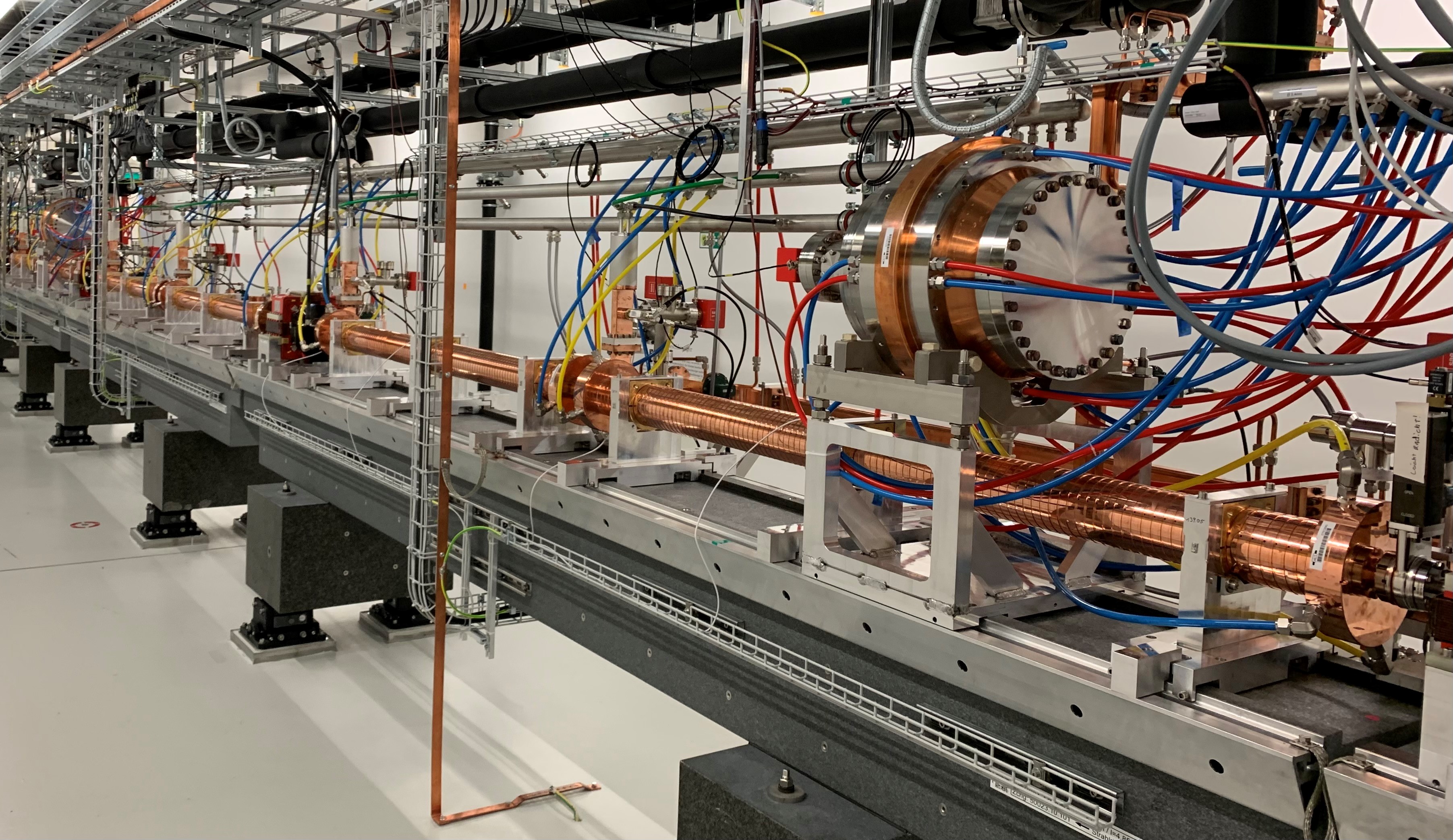 Figure 1: Part of the SwissFEL linac, showing one of the C-band RF modules.
Following the completion of production for SwissFEL and the successful commissioning of the SwissFEL linac, PSI initiated collaborations with CERN, ELETTRA and DESY to extend this production process and expertise to other frequencies, including S-band (3 GHz) and X-band (12 GHz). As an example, two X-band radiofrequency (RF) accelerating structures were constructed as part of a collaborative effort between CERN and PSI for the Compact Linear Collider (CLIC) study. These structures represent a modified "tuning-free" adaptation of CERN's existing design and were assembled using the specialized manufacturing process developed at PSI. The two prototype rf structures underwent rigorous testing, demonstrating exceptional performance. The maximum unloaded gradients achieved were 113 MV/m and 112 MV/m, respectively, with varying RF pulse lengths.
After accumulating a total of 1.4 billion RF pulses, testing culminated with over three days of uninterrupted operation at an accelerating gradient of 103 MV/m and a compressed pulse length of 100 nanoseconds. The testing concluded without any additional breakdowns, yielding an impressive BDR in the 10⁻⁸ bpp range [3]. This successful outcome marks a significant step forward in advancing high-gradient X-band technology for future accelerators.
Another notable example of the application of tuning-free RF technology is the development of S-band accelerating structures in collaboration with Elettra Sincrotrone research center in Trieste (Italy), aimed at upgrading the FERMI Free-Electron Laser (FEL) [4]. FERMI is a fourth-generation light source that operates in the Extreme Ultraviolet (EUV) and soft X-ray spectrum. Currently, there is an ongoing upgrade plan designed to increase the linear accelerator (linac) energy from 1.5 GeV to 2 GeV. This enhancement will be accomplished by replacing older sections of the accelerator with newly designed high-gradient accelerating structures. These new sections can operate at higher gradients while minimizing transverse wakefields, improving overall performance. Following the successful testing of a short prototype of a new high-gradient S-band accelerating structure — capable of sustaining an accelerating gradient of 40 MV/m with a BDR of 8x10⁻⁸ per pulse — two full-length (3.0 m) high-gradient (HG) structures were constructed and installed at the FERMI linac. Currently, these structures are undergoing RF conditioning. One of the two accelerating structures was pre-conditioned at high power on a test stand, reaching the nominal gradient of 30 MV/m with a BDR of 6x10⁻⁸ per pulse. This successful outcome confirms the feasibility of using high-gradient technology within the S-band frequency range [5,6].
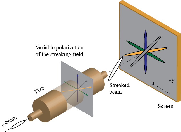
The latest example of application of the tuning-free RF technology concerns the development of a novel concept for transverse deflection structures (TDS) that are well-known diagnostic devices for the characterization of the temporal properties of electron bunches in linear accelerators [7]. TDS-based diagnostic system streaks (or, using the terminology for this type of device, shears or stretches) a charged bunch in the transverse direction by introducing a correlation between the transverse momentum and the longitudinal position in the bunch. This correlation can be used to image the longitudinal distribution of the particles on a screen if a suitable beam optics is used.
One of the main advantages of these TDS-based systems is that the image on the screen represents a single-shot measure of the absolute time profile of the bunch. Furthermore, electron beam diagnostics based on a TDS system placed downstream of the magnetic undulators (post-undulator TDS) in conjunction with an electron beam energy spectrometer can indirectly measure the FEL power profile and the pulse length of these ultra-short photon pulses by analyzing the induced energy spread or the energy loss of the electron bunch due to the FEL process [8]. Several experiments at DESY (FLASH II [9], FLASHForward [10], SINBAD [11]) and PSI (Athos beamline at SwissFEL [12]) were interested in the utilization of high-gradient X-band TDS systems for high-resolution longitudinal diagnostics. In this context, a collaboration between DESY, PSI and CERN was established to develop and build an advanced modular X-band TDS system which included the novel feature of providing variable polarization of the deflecting force.
The possibility of changing the orientation of the streaking field to an arbitrary azimuthal angle opens new opportunities for extended beam characterization which makes particular use of the variable streaking direction, such as 5D phase-space characterization or the retrieval of the three-dimensional charge distribution [13,14]. Combining these novel and more extended beam characterizations with the capability of achieving sub-fs temporal resolution, this diagnostic tool will be able to provide new insight on the multidimensional beam phase-space characterization with sub-fs resolution. Furthermore, this feature allows the measurement of special beam properties such as the slice emittance in different transverse planes. Figure 2 shows a schematic of the longitudinal diagnostic based on the variable polarization of the TDS, the Polarizable X-band (PolariX) TDS [15,16] and a measurement of the electron bunch centroid on a beam position monitor placed after the deflector as a function of the RF phase.
 |
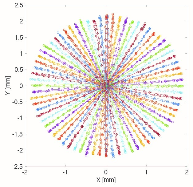 |
Figure 2: Left. Schematic of the longitudinal diagnostic system based on the variable polarization of the PolariX TDS. Right: Measurements of the electron bunch centroid on a beam position monitor placed after the deflector as a function of the RF phase. Polarisation variation of 5 deg.
In recent years, seven PolariX TDSs were built in total by PSI and installed at various facilities. Currently, the two deflectors at FLASH II and the one at FLASHForward are routinely used in operation while the two installed in SINBAD are ready for commissioning. The remaining two structures were installed in the post-undulator diagnostic section of the Athos soft X-ray beamline at SwissFEL. These advanced structures were specifically designed to achieve sub-femtosecond resolution, which is critical for accurately resolving the temporal profiles of soft X-ray pulses. At present, these structures are regularly employed to achieve such tasks as time resolution in the sub-femtosecond (sub-fs) range, a critical capability for capturing the incredibly fast dynamics of soft X-ray pulses [17,18]. Figure 3 shows an example of measurement with the PolariX TDS of a femtosecond-scale energy modulation on an electron beam. This innovative design demands extremely high manufacturing precision to ensure the structure's azimuthal symmetry, which is crucial for preventing unintended rotations of the polarization of the streaking field along the cavity. To achieve this level of precision, the manufacturing relies on the high-precision, tuning-free production process.
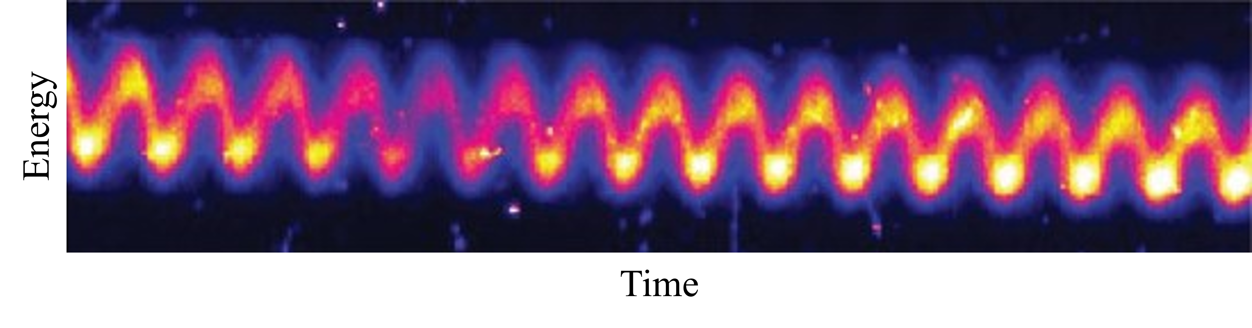 Figure 3: Example of measurement with the PolariX TDS of the induced energy modulation with an external laser at 800 nm corresponding to 2.67 fs.
The knowledge and expertise accumulated by PSI over the last few years in the design, construction, installation, commissioning and operation of SwissFEL, along with solid experience in tuning-free RF technology, have positioned PSI to take on a leadership role. As a result, PSI is now coordinating a comprehensive feasibility study aimed at developing the lepton injector for the Future Circular Collider (FCC-ee) [19]. This injector study is a collaboration between PSI, CERN and several external partners, including CNRS-IJCLab (Orsay, France), INFN-LNF (Frascati, Italy) and KEK (Tsukuba, Japan), involving a team of over forty people.
The FCC-ee injector complex [20] is designed to supply electron and positron bunch trains for alternating bootstrapping injection during both top-up and full injection operations. Given the charge per bucket and the operational lifetime requirements, it is necessary to inject alternating trains of positrons and electrons approximately every few tens of seconds to maintain a balance between positron and electron bunch charges during collider operation. Figure 4 provides a schematic of the latest basic layout of the injector complex. This design includes two distinct linear accelerators (linacs) for electrons and positrons, each accelerating particles to a beam energy of 2.86 GeV. These are the Electron Linac (e-Linac) and the Positron Linac (p-Linac), respectively.
After exiting their respective linacs, both the positrons and electrons are injected into the Damping Ring (DR) to cool down their emittance. The complex also features a High-Energy (HE) linac, which raises the beam energy from 2.86 GeV to 20 GeV, enabling direct injection into the Booster Ring (BR). All linacs, as reported in figure 4, have been optimized for both accelerating gradient and power consumptions, considering capital, infrastructure and operational costs. Moving forward, a preliminary Technical Design Report (TDR) will be prepared in the coming years to guide the future development and construction phases of the injector. The TDR will focus on tuning-free linac technology for RF accelerator structures and related upgrade projects to realize, in cooperation with industry, the approximately 400 RF structures required for injector linacs. The primary goal of the TDR is to outline the detailed specifications for the accelerator and the associated technical infrastructure, ensuring that all system and subsystem requirements are well-defined. This will facilitate the initial civil engineering design, ensuring that the specifications are sufficiently detailed to support the construction phase and the subsequent mass production of components as the rf structures.
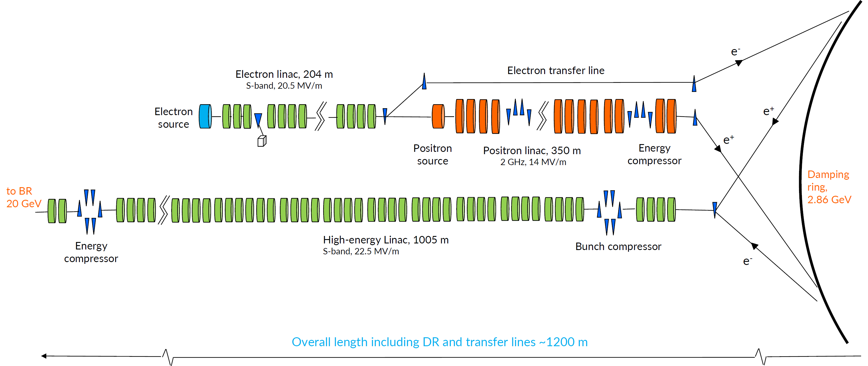
Figure 4: Schematic layout of the FCC-ee Injector complex.
As a conclusion, the ongoing consolidation and extension of the normal conducting tuning-free RF technology developed at the Paul Scherrer Institute marks a significant advancement in accelerator technology, enabling more efficient and reliable performance for future linac based accelerators.
Acknowledgments
This contribution summarizes in a few paragraphs the work of many people at PSI and in the various laboratories with which PSI has collaborated in recent years. Listing all the people is virtually impossible, but I would nevertheless like to take this opportunity to thank everyone for the exceptional work that has led to these outstanding results.
References
[1] E. Prat, R. Abela, M. Aiba et al., “A compact and cost-effective hard X-ray free-electron laser driven by a high-brightness and low-energy electron beam,” Nat. Photonics 14, 748–754 (2020). https://doi.org/10.1038/s41566-020-00712-8.
[2] T. G. Lucas et al., “RF Conditioning and Breakdown Behavior in the C-band Linac of SwissFEL During Commissioning and User-Operation,” submitted to IEEE Trans. Nuclear Sci.
[3] W. L. Millar et al., "High-Power Test of Two Prototype X-Band Accelerating Structures Based on SwissFEL Fabrication Technology," in IEEE Trans. Nuclear Sci. 70 (1), pp. 1-19, (2023), https://doi.org/10.1109/TNS.2022.3230567.
[4] E. Allaria et al., “FERMI 2.0 Conceptual Design Report,” published summer 2022.
[5] N. Shafqat, C. Serpico, T.G. Lucas, “Design and high-power test of a short prototype of high gradient S-band accelerating structure for the FERMI free electron laser linac upgrade,” Nuclear Instruments and Methods in Physics Research Section A 979 (2020), 164473, https://doi.org/10.1016/j.nima.2020.164473.
[6] N. Shafqat, M. Trovo, I. Cudin, R. Fortunati, F. Gelmetti, L. Giannessi, T.G. Lucas, F. Marcellini, C. Masciovecchio, M. Milloch, A. Milocco, R. Zennaro, “Fabrication, conditioning and installation of the 1st high gradient S-band accelerating module for the energy upgrade of the FERMI free electron laser linac,” Nuclear Instruments and Methods in Physics Research Section A 1055 (2023),168543, https://doi.org/10.1016/j.nima.2023.168543.
[7] P. Emma, J. Frisch, and P. Krejcik, “A transverse rf deflecting structure for bunch length and phase space diagnostics,” Reports No. LCLS-TN-00-12 and No. SLAC-PUB-8864, 2000.
[8] C. Behrens, F.-J. Decker, Y. Ding, V. Dolgashev, J. Frisch, Z. Huang, P. Krejcik, H. Loos, A. Lutman, T. Maxwell, J. Turner, J. Wang, M.-H. Wang, J. Welch and J. Wu, “Few-femtosecond time-resolved measurements of X-ray free-electron lasers,” Nat. Comm. 4762 (2014).
[9] E. Ploenjes, B. Faatz, M. Kuhlmann, and R. Treusch, “FLASH2: Operation, beamlines, and photon diagnostics,” AIP Conf. Proc. 1741, 020008 (2016).
[10] R. D’Arcy et al., “FLASHForward: plasma wakefield accelerator science for high-average-power applications,” Phil. Trans. R. Soc. A 377, 20180392 (2019).
[11] U. Dorda et al., “SINBAD: The accelerator R&D facility under construction at DESY,” Nucl. Instrum. Methods Phys. Res., Sect. A 29, 233 (2016).
[12] E. Prat, A. Al Haddad, C.Arrell, et al. “An X-ray free-electron laser with a highly configurable undulator and integrated chicanes for tailored pulse properties,” Nat Commun 14, 5069 (2023). https://doi.org/10.1038/s41467-023-40759-z.
[13] S. Jaster-Merz, R. W. Assmann, R. Brinkmann, F. Burkart, W. Hillert, M. Stanitzki and T. Vinatier, “5D tomographic phase-space reconstruction of particle bunches,” Phys. Rev. Accel. Beams 27, 072801 – Published 3 July 2024.
[14] B. Marchetti et al., “Experimental demonstration of novel beam characterization using a polarizable x-band transverse deflection structure,” Sci Rep 11, 3560 (2021).
[15] P. Craievich et al., “Novel x-band transverse deflection structure with variable polarization,” Phys. Rev. Accel. Beams 23, 112001 (2020).
[16] P. González Caminal et al., “Beam-based commissioning of a novel 𝑋-band transverse deflection structure with variable polarization,” Phys. Rev. Accel. Beams 27, 032801 – Published 8 March 2024.
[17] P. Craievich, Z. Geng, F. Marcellini, C. Kittel, S. Reiche, et al., “Post-undulator beam measurements with PolariX TDS in SwissFEL,” Proc. of SPIE Vol. 12581 1258106-5.
[18] E. Prat, A. Malyzhenkov, C. Arrell, P. Craievich, S. Reiche, T. Schietinger, G. Wang, “Coherent sub-femtosecond soft x-ray free-electron laser pulses with nonlinear compression,” APL Photonics 8, 111302 (2023), https://doi.org/10.1063/5.0164666.
[19] A. Abada, M. Abbrescia, S. S. AbdusSalam et al., “FCC-ee: The Lepton Collider,” Eur. Phys. J. Spec. Top. 228, 261-623 (2019), https://doi.org/10.1140/epjst/e2019-900045-4.
[20] P. Craievich et al., “The FCC-ee Pre-injector complex,” IPAC2022, Bangkok, Thailand, https://doi.org/10.18429/JACoW-IPAC2022-WEPOPT063.