Ankur Dhar, SLAC National Accelerator Laboratory
The recent advances in high gradient research at SLAC have opened new pathways towards a compact energy-efficient Higgs factory [1]. Furthermore, the development of cold copper RF technology stands to benefit other near-term colliders that have a need for high-gradient normal conducting RF accelerators. A crucial milestone in the development of cold copper technology is the demonstration of a functional accelerator module within a cryostat. To that end, substantial progress has been made on maturing cold copper technology towards this demonstration stage.
This progress has included high-power tests of single cavities to record gradients, high-power tests of full meter-long structures, precision alignment and vibration studies in liquid nitrogen and the procurement of a quarter cryomodule (QCM) for integrating all these studies. These updates and more have been actively discussed over the last year, including at a recent workshop at SLAC in February, as part of LCWS2024 in July, and at the C3 workshop in Nikhef in October. Further developments will be highlighted at an upcoming meeting at Duke (details can be found at https://web.slac.stanford.edu/c3/ events).
High-power Tests of Cold Copper
Cooling copper to reach high gradients was demonstrated at X-band, but it is also important to understand these limits at C-band [2-4]. Cavities that were originally designed to test the high-gradient operation of copper versus copper-silver alloy at room temperature were re-tuned for cryogenic operation and tested up to 5 MW per cavity while immersed in liquid nitrogen. These tests were conducted at RadiaBeam, leveraging their high-power C-band infrastructure. As Figure 1 shows, these cavities were able to reach gradients over 250 MV/m, approaching the limits seen in X-band on-axis coupled cavity tests [2]. This gradient would also enable the double flat top RF pulse structure being devised to reduce site power consumption by 25 MW [5]. Following these single cavity tests at RadiaBeam, a similar cryogenic high-power test was performed with a meter-long C-band linac. This test went up to 21 MW into the structure, the test stand limit, demonstrating gradients up to 70 MV/m. Future tests are being planned to reach the ultimate goal of 150 MV/m.
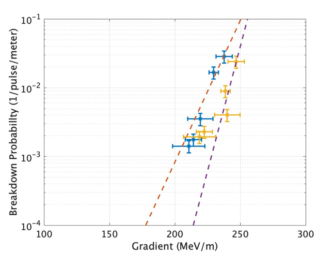 Figure 1: Breakdown rate plot of recent measurements of single cavities from copper (blue) and copper-silver alloy (yellow).
Maintaining Precision Alignment
As with any future collider, C3 will need to preserve each beam’s nanometer scale emittance along the 3 km main linac. Benchmarking this capability is being done through simulation and experimental characterization. The simulation work has focused on the main linac’s beam dynamics to determine the required damping and detuning needed to minimize expected wakefield kicks to the beam. Detuning can be accomplished through subtle adjustment of nose cone gaps between individual cavities within a single meter-long structure [6]. Meanwhile damping slits lined with a lossy conductor can suppress high-order modes and reduce long-range wakefields. Further work is being done to evaluate the impact of halving the bunch spacing, which has the potential to reduce site power consumption to 110 MW [5]. Nichrome is a promising candidate for this lossy conductor, as it shows resilience to high gradients, low temperatures and hydrogen brazing; all while maintaining a conductivity 100 times lower than copper at room temperature. Our simulations show that by utilizing both techniques, beam emittance can be maintained to within 10 nm with up to micron-scale displacements of individual accelerating structures [7].
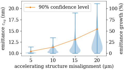 Figure 2: Estimated beam emittance from single bunch simulations to ELEGANT with randomly distributed misalignment to accelerating structures. Current C3 parameters suggest that a misalignment tolerance of 5µm is enough to keep emittance growth within 10%.
Figure 3: RMS vibration measurements in the Y-direction during high power tests at RadiaBeam (a), and via a resistive heating element to approximate the full thermal load (b). Both of these measurements suggest that the overall contribution to linac displacement from liquid nitrogen boiling is within a micron.
Alongside this work, experiments are being conducted to characterize the unique vibration spectrum stemming from immersion in liquid nitrogen. During operation, the heat load per meter is expected to be around 2.5 kW of average power. This heat is rapidly conducted away by nuclear boiling, but bubbles on the underside of the structure can cavitate and induce minute impulses that misalign the structure. These experiments utilized a prototype C3 structure immersed in liquid nitrogen and outfitted with a resistive heater inside the beam pipe. This heater allows up to 2 kW of heat to be deposited into the structure to approximate this heat load. Induced vibrations in each axis are measured with accelerometers to determine the RMS displacement induced by the applied heat load [8]. Similar measurements were also done during the meter-long structure test at RadiaBeam to provide a direct comparison to this trial experiment. Future experiments are being planned with an accelerating structure and quadrupole magnet mounted within a cryomodule. In both cases, it was determined that the RMS displacements were well within the expected tolerances based on simulation, as shown in Figure 3. This is a promising result to demonstrate that cryogenic operation is possible while preserving low-emittance beams.
 |
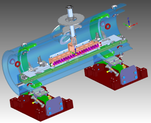 |
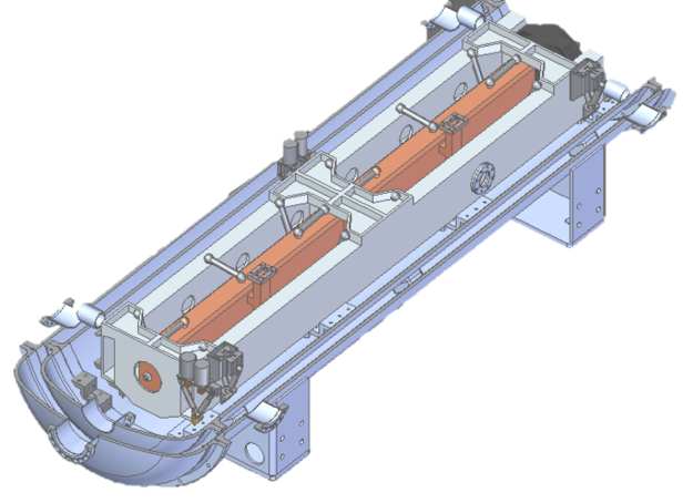
Figure 4: Mechanical designs for rafts accommodating C-band structures (a), as well as S-band injector linacs (b).
Another path to improving emittance preservation is to increase the beam aperture, thereby reducing the impact of wakefields. However, this usually comes at the cost of shunt impedance, thereby impacting efficiency. Recent work on distributed coupling has shown that the sweet spot for balancing these two parameters occurs when the cavity phase advance is 135 degrees, as opposed to the 180 degree phase advance currently used [9]. Careful design of the power distribution manifold has made it possible to realize this phase advance with two separate manifolds. This means the structure can still be made from two slabs as previous distributed coupling structures have been made, retaining the existing performance demonstrated with current prototypes structures while improving emittance preservation. Future investigation will probe the possibility of powering the accelerating structures with RF pulse compression, which could reduce site consumption by 30 MW.
Quarter Cryomodule Plans
Individually, each of these advances are promising steps forward for cold copper technology, so the synthesis of all these improvements into one complete demonstration is an important future milestone. To accomplish this, a quarter cryomodule (QCM), the smallest repeating block of the main linac, is being manufactured and is expected to arrive this fall. A single cryomodule is designed to accommodate eight meter-long structures and four quadrupole magnets on four rafts, so the QCM will house one raft with two meter-long structures and one quadrupole magnet. Some of the tests already planned with the QCM include thermal load tests on the liquid nitrogen bath, alignment tests with a Rasnik system while immersed in liquid nitrogen [10], and structural tests of several prototype raft designs which will support the accelerating structures and quadrupole within the cryomodule, as shown in Figure 4. This will pave the way for eventual high RF power and beam tests in the future, providing a key demonstration of cold copper technology for high energy physics and the accelerator community at large.
[1] C. Vernieri,et. al, Journal of Instrumentation 18 (07), P07053.
[2] A. D. Cahill, J. B. Rosenzweig, V. A. Dolgashev, S. G. Tantawi, and S. Weathersby, Phys. Rev. Accel. Beams 21, 102002 (2018).
[3] S. Tantawi, M. Nasr, Z. Li, C. Limborg, and P. Borchard, Phys. Rev. Accel. Beams 23, 092001 (2020).
[4] M. Nasr, E. Nanni, M. Breidenbach, S. Weathersby, M. Oriunno, and S. Tantawi, Phys. Rev. Accel. Beams 24, 093201 (2021).
[5] M. Breidenbach, B. Bullard, E. A. Nanni, D. Ntounis, and C. Vernieri, PRX Energy 2, 047001 (2023).
[6] Z. Li, in Cold Copper Accelerator Technology and Applications Workshop (2023).
[7] W.-H. Tan, in LCWS2024 (2024).
[8] A. Dhar, Vibration Analysis of Cryogenically Cooled Accelerating Structures, Tech. Rep. SLAC-PUB-17776 (SLAC, 2024).
[9] M. Shumail, in LCWS2024 (2024).
[10] H. van der Graaf, et. al, “The alignment of the c3 accelerator structures with the rasnik alignment system (2023),” arXiv:2307.07981 [physics.acc-ph].