Hans Braun, Philip R. Willmott, Alun Ashton, Romain Ganter, Markus Jörg, Paul Scherrer Institute, CH-5232 Villigen, Switzerland
The Swiss Light Source (SLS) at the Paul Scherrer Institute (PSI) delivered its last photons on 30th September 2023 before undergoing a comprehensive upgrade to a diffraction-limited storage ring (DLSR) housed in the existing building (Figure 1). Some 18 months later, in early April 2025, the new SLS 2.0 was already storing the nominal full 400-mA beam-current two and a half months after injecting the first electrons (Figure 2) .

Figure 1: The renovated SLS building housing now SLS 2.0, showing the new aluminum roof fitted with solar panels.
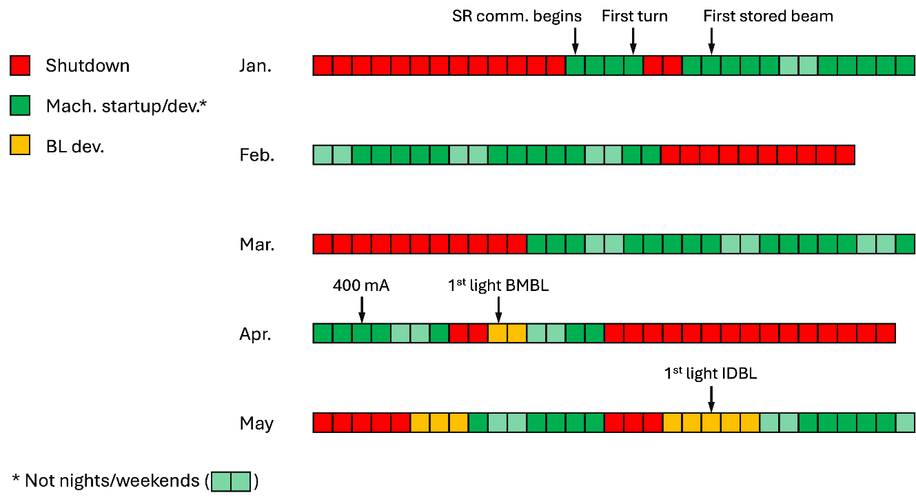
Figure 2: Timeline of the most important milestones in the commissioning of SLS 2.0. Note that from beginning of commissioning (14.01.2025) to attaining the nominal storage-ring current of 400 mA (03.04.2025) took 43 commissioning days, highlighted in green. Weekends and night shifts were dedicated to vacuum conditioning (light green).
The upgrade program has been defined by several innovations and features which have been largely dictated by the relatively small footprint of the storage ring—as a rule of thumb, the brilliance scales with the cube of the ring circumference. Although the dimensions of both the new arcs and straights differ from those of the original SLS, the concrete housing and the booster ring that reside in the same tunnel as the storage ring meant that any new design could not differ substantially in circumference—indeed it emerged that both the old and new ring have the same circumference of 288 m. Moreover, the design current of 400 mA and the RF frequency (500 MHz) remain unchanged.
The challenge of designing a fourth-generation storage ring with such a modest circumference was met thanks to a multi-bend lattice incorporating reverse-bend magnets [1-3] based on permanent magnet technology [4, 5]. Reverse bends provide a small deflection of the electron beam opposite the main bending magnets that can be adjusted to ensure minimal dispersion of the electron beam precisely at the center of the bending-magnet dipoles.
The new ring is based on twelve 7-bend-achromat arcs; each arc has a total length of 18 m. This high-density configuration demands the use of permanent magnets to a large extent, as electromagnets would have proved to be too bulky to be installed in such a cramped environment (see Figure 3). This has the added benefits of (a) reducing significantly the facility's power consumption; and (b) providing an intrinsically stable beam, as the magnetic fields, being permanent, are unaffected by fluctuations in electromagnet currents. Consequently, much effort had to be invested to avoid significant crosstalk between neighboring magnets [5]. The limited space for magnet length also imposed a smaller aperture to achieve a large enough magnet strength, which in turn led to a vacuum chamber inner diameter of only 18 mm. The whole inner surface of the copper arc vacuum chambers was NEG coated to speed up the vacuum conditioning with beam. The beam current was increased from 20 mA to the nominal 400 mA in about one month [6], leading to an average pressure without beam close to 10-11 mbar. The fast-orbit feedback operating at 40 kHz provides a beam stability in both the vertical and horizontal planes of 150 nm FWHM.
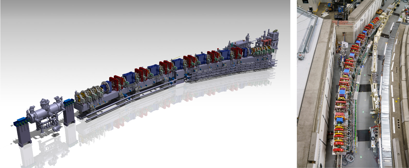
Figure 3: Left: technical 3D-rendition of Straight 2 and Arc 2 at SLS 2.0. Right: Straight and Arc 12, also showing the injection chamber from the booster ring to Straight 1.
Even though the minimum electron-beam horizontal emittance of a storage ring is proportional to the square of the storage-ring energy (ξ), it was decided to increase this from 2.4 GeV previously to 2.7 GeV in the new machine. This was motivated by the similar observation that the intensity of a given undulator harmonic is also proportional to ξ2 -- since the days in which the design specifications of the original SLS were decided upon in the 1990s, accelerator-based photon science at the PSI has, on average, drifted towards higher photon energies, particularly in the fields of scattering/diffraction and lensless imaging. As the original booster ring continues to be used in SLS 2.0 and was designed to ramp up energy to as high as 2.7 GeV, this feature was exploited accordingly.
The 500 MHz main RF system of the ring has been completely renewed using four HOM-damped single-cell copper cavities, each fed by a 150-kW solid-state amplifier. The passive superconducting two-cell third-harmonic cavity of the old SLS has been re-used.
No impedance-driven collective instabilities have been seen up to the nominal beam current.
The SLS 2.0 operates with a 4-bump injection similar to the previous ring but now uses a split-septum configuration with a thick septum of permanent magnets followed by a pulsed thin septum close to the stored beam. In the thin septum, the injected beam is only 3 mm away from the stored beam, separated by a 1-mm-thick sandwich of copper and iron foils. Typical injection efficiencies from booster to ring are better than 80% during filling and topping-up. Typical lifetimes at nominal current are 10 hours. The machine-protection system is augmented with a beam dump kicker, a dedicated beam dump, and two transverse collimators, to reduce the risk of damage by uncontrolled beam loss [7].
Figure 4 is a so-called Bartolini plot of third- and fourth-generation synchrotron facilities. In such a plot, the emittance is weighted by the inverse square of the storage ring electron beam energy γ expressed in units of the electron rest-mass energy, to “even the playing field” on account of the fundamental limit of the horizontal electron emittance being proportional to the square of the storage ring energy. The dotted guidelines have a gradient of –3 on this double-logarithmic graph, as the lower limit to the emittance scales with the inverse cube of the encompassed angle of each dipole element in the arcs, which itself is approximately proportional to the storage-ring circumference.
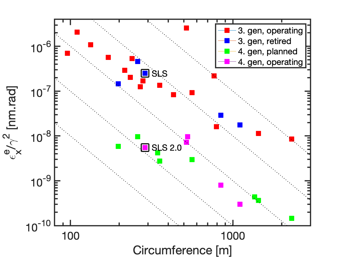
Figure 4: Bartolini plot of third- and fourth-generation synchrotron facilities showing the horizontal electron emittance weighted by the inverse square of γ as a function of the facility circumference. The upcoming fourth-generation facilities in green include both planned facilities and those still under construction. The original SLS and the upgraded SLS 2.0 are highlighted by black borders. The dotted lines represent the theoretical relationship between the weighted emittance and circumference for a given machine performance; each line is separated from its neighbor by one order of magnitude.
Combined, the above-described features mean that the new ring delivers a horizontal electron emittance of 157 pm·rad, an improvement of 35 compared to the previous SLS ring.
The beamline portfolio of the 18-user beamlines is shown graphically in Figure 5. Of these, only two, XIL and ADDAMS (formerly MS) continue to use the same sources as in the original SLS (U70 and CPMU14, respectively).
Most of the x-ray sources in the straights are replaced by new devices. Four of the hard x-ray ID beamlines now use 3-m in-vacuum U17 undulators with magnetic force compensation. The soft x-ray beamlines use combinations of Apple-III and Apple-X [8-10]. Those beamlines that have an upper limit to their photon energy below 2 keV use only the fundamental and can thus exploit the novel "knot'' design, in which the higher harmonics are in an outer cone and can thus be removed in the frontend by an aperture, thereby much reducing heat-load problems and associated undesired vibrations due to the otherwise necessary aggressive cooling schemes of the beamline optics and components.
Another R&D project being pursued concerns a novel insertion device exploiting high-temperature superconducting bulk material as part of the SLS upgrade program and integrated into the CHART and LEAPS Innovation program. The goal is to generate undulators with ultra-short-period (10-mm) and high magnetic field strengths. For medium-energy synchrotron storage rings such as SLS 2.0, this is a promising route to significantly extend the photon flux from insertion devices to energies well beyond 50 keV. The so-called 'HTSU10', with a 1-m magnetic length, will replace a U15 in-vacuum undulator at the new I-TOMCAT beamline in 2027 [11, 12].
Of the seven bending-magnet user beamlines, three (VUV, PolLuX, and ISS) use the standard 1.35-T dipoles of the 7-bend achromats; two (PXIII and SuperXAS) use warm 2.1-T superbends; and a further two (S-TOMCAT and Debye) are equipped with 3- to 5-T variable-field NbTi superconducting superbends [13].
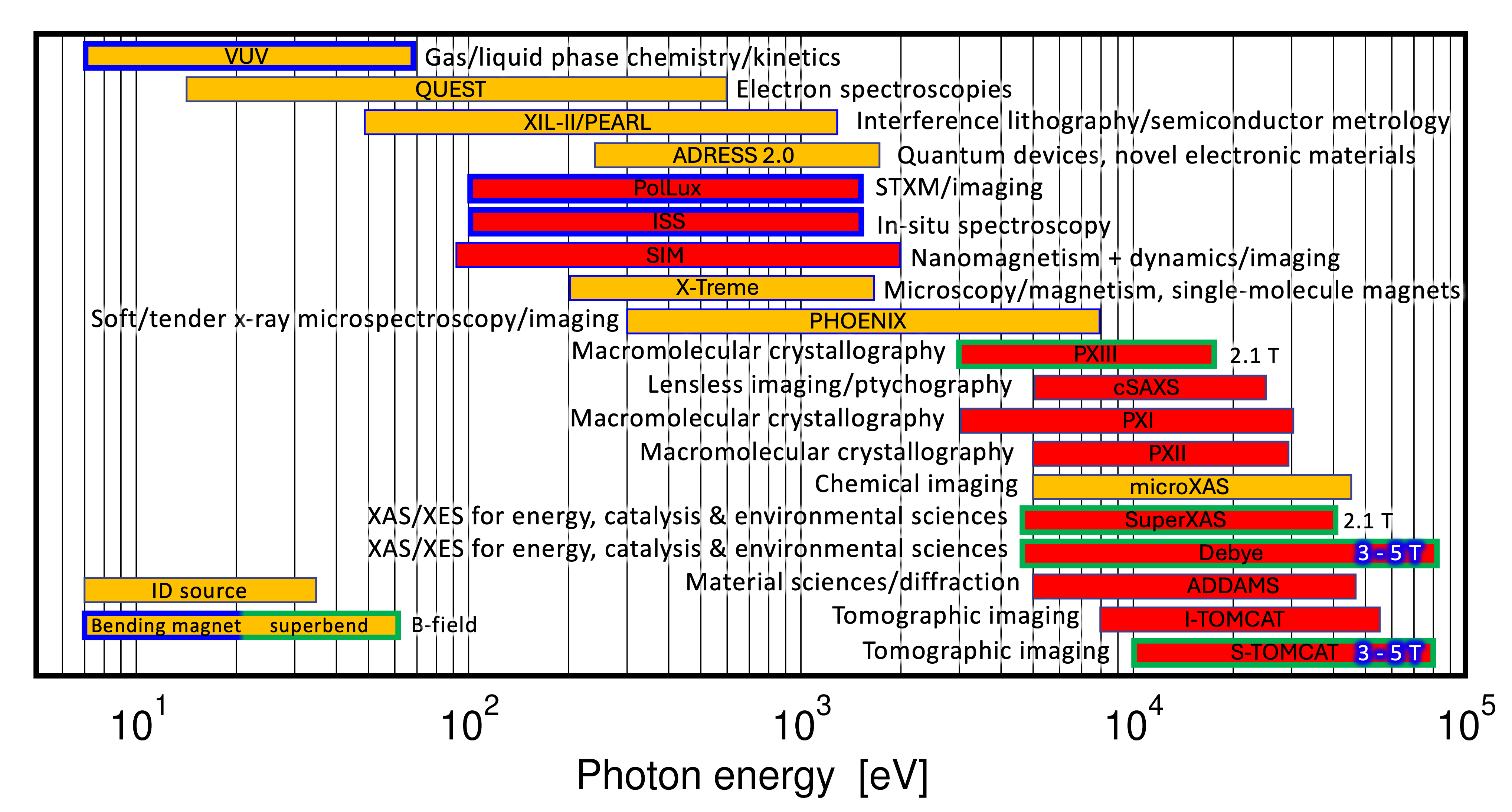
Figure 5: Beamline portfolio at SLS 2.0. Those beamlines highlighted in red have, by November 2025, taken first light and are either commissioning or hosting pilot users; beamlines in orange are expected to complete commissioning and take first users before the end of 2025; the remaining beamlines will begin commissioning, most starting in the second semester of 2026 after the second shutdown required to insert the superconducting superbends and the remaining insertion devices. Beamlines with undulator sources have thin black borders, while those with bending magnets (1.35 T) have thick dark blue borders, and the warm superbends (2.1 T) and cryocooled superconducting superbends (3 – 5 T) have thick green borders.
All 18 of the beamline frontends at SLS 2.0 have undergone comprehensive updates, motivated by the increased power of the synchrotron beam, changing source points, new safety regulations, and enhanced beam properties. These new designs feature innovative and enhanced cooling systems to manage the high-power load and meet new requirements such as mechanical stability and compact footprints [14].
Most of the hard x-ray beamlines have benefited from a significant optics upgrade program [15]. Monochromators and mirrors have been redesigned with the reduced horizontal breadth of the photon beam at SLS 2.0 in mind. New crystal and multilayer monochromators scatter and disperse the incident radiation in the horizontal plane; the minor loss in intensity due to polarization factors is more than offset by the benefit of horizontal rotational movements, allowing compact and stable designs. Horizontally deflecting and focusing mirrors are also significantly shorter and thereby gain in stability.
By November 2025, twelve of the 18 user beamlines have received first light; nine of these have already performed first pilot experiments, while five (PolLux, SuperXAS, Debye, PXIII, and ADDAMS) are hosting users in a limited round of official proposals in the last two months of 2025. (see Figure 5). By the end of 2026, most beamlines will be back in full user operation, except for ADRESS and QUEST, which require more time to install their undulators, and microXAS, which is relocating to a new straight.
A key IT challenge was to integrate legacy and modern computer and electronic systems. To address this, EPICS 7 is being used to unify all components, ensuring that both old and new monitoring and control systems appear consistent from the operator’s perspective; consequently, the startup and commissioning of the accelerator has proceeded smoothly.
The accelerator control system demonstrates well the seamless integration of heterogenous platforms. Low-level RF and diagnostics are fully implemented by the new platform. It was also ensured that the timing system is backward compatible. For the beamlines, outdated VME motion controllers have been replaced with ECMC (EtherCAT Motion Controller) modules using Beckhoff drivers. This upgrade provides beamline scientists with a flexible, safety-integrated system and a wide range of configuration options.
Before the upgrade, the landscape of measurement tools used at the SLS beamlines was quite heterogeneous with solutions implemented in different frameworks and toolkits, incompatible interfaces, and limited collaboration opportunities, making them hard to maintain. The upgrade project was thus an opportunity to consolidate these into a unified new ``Beamline and Experiment Control'' (BEC) system. Built on community tools like the ophyd hardware abstraction layer, BEC uses a client-server architecture. The server consists of modular services that communicate via a Redis-based message broker and an in-memory database.
This design separates concerns, speeds up development of internal services, and simplifies integration of new services, data analysis routines and external systems through shared memory access [16].
The roof of the SLS has been replaced with an aluminum construction, on top of which solar panels are integrated over approximately half the roof area (Fig. 1). This provides energy production of approximately 900 MWh per year. This, along with the replacement of electromagnets of the old lattice with permanent magnets in SLS 2.0, the use of solid-state RF power amplifiers instead of klystrons, and power-efficient new cooling infrastructure, means that the total yearly net power consumption of the facility, including beamlines and infrastructure, drops from approximately 23 GWh to 15 GWh.
References
[1] A. Streun, “The anti-bend cell for ultralow emittance storage ring lattices”, Nucl. Instrum. Methods A, 737, 148154 (2014).
[2] A. Streun, A. Wrulich, “Compact low-emittance light sources based on longitudinal gradient bending magnets”, Nucl. Instrum. Methods A, 770, 98112 (2016).
[3] A. Streun, “Upgrade of the Swiss Light Source storage ring based on a lattice combining longitudinal gradient bends and anti-bends”, ICFA Beam Dynamics Newsletter, 71, 213 (2017)
[4] C. Calzolaio et al., “Overview of permanent magnet implementations for advanced light sources”, in Proc. 16th International Particle Accelerator Conference, 24 (2025).
[5] M. Aiba et al., “Magnet crosstalk in highly-compact light-source storage ring”, in Proc. 16th International Particle Accelerator Conference, 201 (2025).
[6] M. Böge, “SLS 2.0 storage ring commissioning”, in Proc. 16th International Particle Accelerator Conference, Taipei, Taiwan, June 2025, paper WECN1 (2025).
[7] R. Ganter, “SLS 2.0 storage ring upgrade overview”, in Proc. 16th International Particle Accelerator Conference, Taipei, Taiwan, June 2025, paper MOPB005 (2025).
[8] F. Ji et al., “Design and performance of the {APPLE-Knot} undulator”, J. Synch. Rad., 22, 901 (2015).
[9] X. Liang et al., “Analysis of the first magnetic results of the {PSI APPLE X} undulators in elliptical polarization”, Nucl. Instrum. Methods A, 987, 164741 (2021).
[10] S. Richter et al., “First magnetic experience with Apple-X Knot undulators for SLS 2.0”, in Proc. 16th International Particle Accelerator Conference, Taipei, Taiwan, June 2025, paper TUPM068 (2025).
[11] M. Calvi et al., “A GdBCO bulk staggered array undulator”, Supercon. Sci. Technol., 33(1), 014004 (2019).
[12] K. Zhang et al., “Record field in a 10 mm-period bulk high-temperature superconducting undulator”, Supercon. Sci. and Technol., 36, 05LT01 (2023).
[13] C. Calzolaio et al., “Longitudinal Gradient Bend Magnets for the Upgrade of the Swiss Light Source Storage Ring”, IEEE Trans. Appl. Supercon., 30, 1 (2020).
[14] D. M. Just et al., “Upgraded front ends for SLS 2.0 with next-generation high-power diaphragms and slits”, J. Synch. Rad., 31, 1582 (2024).
[15] B. Rösner et al., “The concept for hard X-ray beamline optics at~SLS~2.0”, J. Synch. Rad., 31, 771 (2024).
[16] A. Ashton et al., “The Controls and Science IT Project for the SLS 2.0 Upgrade”, in Proc. 19th Int. Conf. Accel. Large Exp. Phys. Control Syst (ICALEPCS’23), Cape Town, South Africa, October 2023, p. 1616 (2023).