Reducing Drag to make Ships Go Further with Less Fuel
Ships use large quantities of fuel to provide the propulsive power necessary to overcome resistance to their motion across ocean surfaces. Over the years, many techniques have been proposed to reduce this resistance and, therefore, increase a ship’s fuel efficiency. The resistance a ship encounters in the water, also called "drag", is usually divided into "form drag", which is due to the shape of the ship’s hull, and "frictional drag", which is due to the friction between the liquid and the ship’s moving hull. Frictional drag is a significant part of the overall resistance, and ship operators have known for years that a smooth hull free of "fouling" will lead to higher ship speeds and fuel savings. A much larger reduction in the frictional drag can be achieved if the water is moved away from the surface entirely. This is done by creating a layer of air between the ship and the flow. This idea, called "air lubrication" has been the dream of naval architects since the 19th century. But, to date, only a few ships have successfully been able to employ air lubrication effectively. The goal of our research is to understand the physical processes that take place in large-scale flows that are lubricated with layers of air so that they may be effectively used to reduce the drag on ocean-going ships.
Air lubrication can be achieved in one of two ways: air can be injected on the ship's hull to form a thin layer, or an indentation can be made in the hull to hold a pocket of air. The first type of air lubrication is called "Air Layer Drag Reduction" and the second kind "Partial Cavity Drag Reduction". When the air layers or cavities are properly formed, they can reduce skin friction over the air covered surface to almost nothing. While it requires energy to pump the air under the ship, we believe that the net overall energy savings on a typical large ship could be between 10% and 20% of the overall fuel expenditure if air lubrication if successfully implemented. This could be a significant fuel savings given that ships across the world use over 2.7 billion barrels of fuel oil per year (8.6% of world’s oil supply) [1] and they also emit over 1 billion tons of CO2 annually. Shipping accounts for 2% of CO2, 16% of SOx(from petroleum sources) and 14% of NOx emissions worldwide [2].
A simple test to illustrate how air lubrication works is to run a thin but sturdy sheet, or even your hand, through air and then through water while keeping the widest area on the sides. The resistance you feel, if you used a thin sheet, is mostly due to frictional drag, and you can immediately observe that the resistance in air is much less than in water. This is because the dynamic viscosity (that is, the natural resistance to flow) and density of air are much less than those of water. In fact, the frictional drag is more than 500 times greater in water than it is in air.
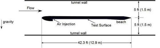
The experiments on which we report were performed at the W.B. Morgan Large Cavitation Channel. This U.S. Navy facility is the largest water tunnel in the world, and it allowed us to perform the experiments at near real-world scales while remaining in controlled laboratory conditions. The model used to represent a ship's hull bottom was 3 meters (10ft) wide and 12.9 meters (42ft) long. About a meter from the front of the model was a 7 inch deep step behind which air was injected. Air fills the cavity recess between the step near the front of the model and a "beach" near the end of the model. The beach is a specially shaped feature used to prevent air from escaping in bulk from the cavity. Minimizing the escaping air is an important feature implemented to reduce the energy consumed by this drag reduction technique. The frictional drag on the surface covered by air is reduced greatly (measured local drag reduction was more than 95%). The figure below shows a side view of the experimental setup.
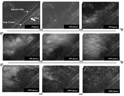
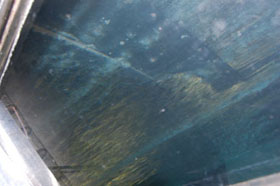
The next figure exhibits a time series of photos as the cavity fills with air. The view was recorded looking from beneath at the back face of the step and injector. After 2.5 seconds the cavity is filled and its surface resembles glass art with fine ripples and streaks.
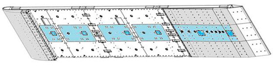
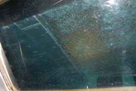
To measure the frictional forces the test surface was instrumented with "shear stress" sensors. High-speed video and electrical "impedance" probes were used to observe the air cavity formation and its subsequent behavior. The flow speed was measured using a laser instrument called the Laser Doppler Velocimeter. At the cavity closure (where the continuous cavity terminates) large clouds of bubbles were shed [3]. This shedding process closely resembled that occurring in "natural" cavitation such as occurs in propellers. In the drawing below, the model's lower surface is shown with the nose and beach colored grey and shear stress sensors light blue. The photos show the cavity surface as seen from below – at the step and at the beach.
These experiments were the sixth phase of a systematic research program investigating the use of bubbles, polymers, air layers and air cavities to reduce drag. In addition to the aforementioned measurements we have recorded pictures and video, and have published articles, many of which are available at our website: www.umich.edu/~ceccio/air.
This series of large scale experiments is scheduled to continue in the summer of 2009 with a new two-month test, which aims to answer remaining questions about the design and suitability of cavities. If the results are positive, an actual sea-trial might be justified. Our research group is also conducting small scale experiments to increase the understanding of the underlying physical processes of air layers and cavities as techniques for practical drag reduction.
References
- Reuters, http://www.reuters.com/article/pressRelease/idUS82323+24-Jun-2008+BW20080624
- http://www.epa.gov/region09/air/marinevessel/pdfs/long.pdf
- Lay K. A. et al. "Partial Cavity Drag Reduction at High Reynolds Numbers" Submitted to Journal of Ship Research.