Past Meetings

Image Descriptions 2008

Carbon Dioxide-Absorbing Aqueous Brine

Christophe Wylock, Sam Dehaeck, Alexey Rednikov, Pierre Colinet
Chemical Engineering Dept, Free University of Brussels

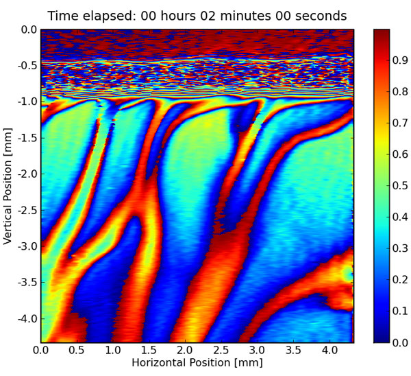
One step in the production of baking soda consists of absorbing carbon dioxide into a liquid mixture. When the carbon dioxide enters this liquid, a chemical reaction occurs, capturing the carbon dioxide into a baking soda molecule. As this is heavier than the starting liquid, these molecules sink to the bottom of the mixture, giving more room for other carbon dioxide molecules to be captured. In the image, two of these downward jets are visualized by means of digital holographic interferometry.

colinet_CO2absorption.jpg

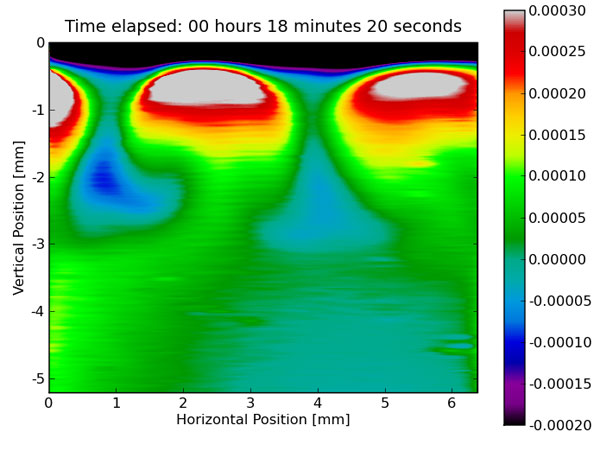
The emission of carbon dioxide into the atmosphere of typical chemical industries can be reduced by absorbing carbon dioxide into optimized liquid mixtures. When the carbon dioxide enters these liquids, a chemical reaction occurs, capturing the carbon dioxide into a new chemical molecule. As the newly formed molecule is heavier than the starting liquid, these molecules sink to the bottom of the mixture, giving more room for other carbon dioxide molecules to be captured. In the image, multiple trains of these new molecules that are transported downwards are visualized by means of digital holographic interferometry.

colinet_MEA.jpg

cocktail_2.jpg

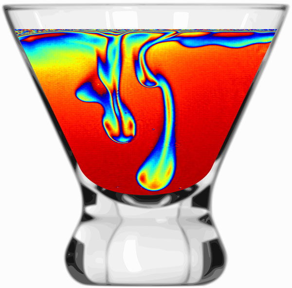
When a mixture of water and alcohol is evaporating, the alcohol will evaporate faster. As a result, the liquid at the surface will contain relatively more water than the rest of the cocktail. This corresponds to a heavier liquid and therefore it sinks to the bottom of the glass. In the image, such sinking, water-rich structures are visualized by means of digital holographic interferometry.

This work was supported by F.R.S.- F.N.R.S. (Belgian National Fund for Scientific Research); CIMEX-PRODEX Programme managed by the European Space Agency in collaboration with the Belgian Federal Science Policy Office, and by the ARCHIMEDES (ARC 04/09-308) project funded by the Communauté Française de Belgique.

References
The image Carbon Dioxide-Absorbing Aqueous Brine appeared in "Chemo-hydrodynamical instability created by CO2 absorption in an aqueous solution of NaHCO3 and Na2CO3" by Christophe Wylock, Sam Dehaeck, Alexey Rednikov, and Pierre Colinet in Microgravity -- Science and Technology, Volume 20, Numbers 3-4 / September 2008. See: http://www.springerlink.com/content/hp7v05773g7q/?p=1133d99b97064c3a81bb1ccd3eef6fa4π=0

The image Carbon Dioxide-Absorbing Aqueous Brine has not been published.

The image Carbon Dioxide-Absorbing Aqueous Brine cocktail image: not yet published in this form

A similar image (the base image without the cocktail-glass) was published in "A Mach-Zehnder interferometer-based study of evaporation of binary mixtures in Hele-Shaw cells" by S. Dehaeck, Ch. Wylock, and P. Colinet, XXIII International Symposium on Flow Visualisation ISFV13 – XXII French Congress FLUVISU12 (Nice, France, 1-4/07/2008)

Splash-Rebound of a Viscoelastic Drop

R. Zenit 
Instituto de Investigaciones en Materiales, Universidad Nacional Autonoma de México

zenit-tn.jpgSome materials are elastic solids; some others are viscous liquids. There is a class of materials which has properties of both solids and liquids: their properties are viscoelastic. Such fluids (solids?) can be found in nature and industry. In this sequence of images, the collision of a viscoelastic drop (or particle) is observed with a high speed camera. If the particle were a solid, it would deform upon collision and rebound. If it were a liquid, it would splash and flow. For a viscoelastic drop we observe that both processes can be observed: first, when the drop touches the wall, it spreads and begins to splash; after a certain time, the material 'remembers' its original state and begins to recoil; the drop reforms and a rebound is observed. Such simple observations help us to understand the properties of viscoleastic materials.

This work was supported by UNAM.

This image has not been published.

A Miniature Explosion within a Droplet

G. L. Heijnen,
Physics of Fluids, Faculty of Sciences, University of Twente, The Netherlands

P. A. Quinto-Su,
School of Physical and Mathematical Sciences, Division of Physics and Applied Physics, Nanyang Technological University, Singapore

X. Zhao,
School of Physical and Mathematical Sciences, Division of Physics and Applied Physics, Nanyang Technological University, Singapore

C.D. Ohl,
School of Physical and Mathematical Sciences, Division of Physics and Applied Physics, Nanyang Technological University, Singapore

droplet-tn.jpgA miniature explosion initiated within a droplet of 6 mm diameter and sitting on a glass plate leads to the upward ejection of a fast liquid jet. The explosion generated with a pulsed laser creates an expanding and then shrinking bubble. During the shrinkage of this bubble a second jet is formed, which surrounds the faster inner one. Both jet tips become instable, the inner jet forming a spherical droplet at its highest point, the outer one creates a crown shaped tip structure. A careful look into the droplet reveals the remains of the bubble arranged on a ring.
The picture is taken 0.4 milliseconds after the explosion with a consumer digital SLR camera (D200 from Nikon), a macro lens, and a home built strobe using a high power light emitting diode (P7 from Seoul Semiconductor).


The work is supported by Nanyang Technological University, Singapore.

The picture has not been published.

Film Instabilities in Microchannels

Thomas Cubaud
Department of Mechanical Engineering, Stony Brook University, Stony Brook, NY 11794-2300
http://me.eng.sunysb.edu/~microfluidics/

Figure 1

Figure 1: Formation of droplets (ethanol) during the folding instability of a capillary viscous thread (silicone oil) in a diverging slit microchannel. The thread deformation introduces variations in the thickness of the sheath fluid’s film between the thread and the top and bottom walls (glass); the film ultimately ruptures into droplets along coalesced folds.

Figure 2

Figure 2: Formation of droplets due to the interplay between the dynamic wetting of the sheath fluid (silicone oil) at the top and bottom walls (glass) and the lubrication failure of a capillary viscous thread (mineral oil) in a diverging slit microchannel.

Detailed Description
These droplet-decorated streams are observed through the glass of a diverging microchannel. Microfluidic devices allow for exploring original fluid interactions far from equilibrium. Here, a combination of hydrodynamic instabilities is used for continuously producing droplets. Upstream (top), a thread made of viscous fluid flows in the center of a square channel. The thread is surrounded in a sheath of immiscible, less viscous fluid at the walls. Downstream, the thread buckles and feeds a slowly moving pile, which is in contact with the glass walls of the diverging channel. In the contact region, droplets form due to the inclusion of the ensheathing fluid into the pile. Figure 1 displays tiny droplets sliding on tracks. The thread’s buckling deformations create local variations of the less viscous fluid’s film thickness at the walls. When the film is thin enough, it destabilizes and ruptures, or “dewets”, into droplets. Figure 2 shows the side embedding of droplets into the pile. This phenomenon results from the interplay between the fluids’ partial wetting of the walls and the thread’s lubrication failure. These images show the possibility to structure microflows and illustrate the importance of solid walls confinement and material properties on microscale multi-fluid dynamics.

This research was supported the Dept. of MEC and CEAS at Stony Brook University.

These images have not been published.

Swimming by Jet Propulsion

Kelly Rakow Sutherland,
MIT/WHOI Joint Program in Oceanography

Alexandra H. Techet,
Department of Mechanical Engineering, Massachusetts Institute of Technology

Larry P. Madin,
Woods Hole Oceanographic Institution

sutherland-tn.jpgThe image above shows a jet wake produced by the salp, Cyclosalpa affinis. Salps, or pelagic tunicates, are common gelatinous organisms in oceanic waters. They swim by jet propulsion, drawing water through incurrent (oral) and excurrent (atrial) siphons at opposite ends of the body. The jet wake in the image was made visible using fluorescein dye during a night SCUBA dive. The authors of the study are looking at propulsive jet wakes to compare distinct swimming styles among different species of salps.

The work is supported by the National Science Foundation (OCE-0647723).

This image has not been published. (Credit: K.R. Sutherland)

An Iron Drop in a Magnetic Field

ching-tn.jpgChing-Yao Chen
National Chiao Tung University, Taiwan, R.O.C.

W.-K. Tsai,
National Yunlin University of Science & Technology, Taiwan, R.O.C.

The miscible interface of a ferrofluid droplet under the influence of a vertical magnetic field.

Sphere Passing Through Corn Syrup

Roberto Camassa
Claudia Falcon
Richard M. McLaughlin
Nicholas Mykins
University of North Carolina

Roberto Camassa,
Applied Mathematics, University of North Carolina at Chapel Hill.

Claudia Falcon
University of North Carolina at Chapel Hill.

Joyce Lin 
Applied Mathematics, University of North Carolina at Chapel Hill.

Richard M. McLaughlin,
Applied Mathematics, University of North Carolina at Chapel Hill,

Nicholas Mykins,
University of North Carolina at Chapel Hill

Overlaid images of a sphere entraining dyed corn syrup as it passes through the density transition in a strong, stable stratification of miscible fluids. At low Reynolds, the sphere can been seen to slow down beyond the terminal velocity of the bottom denser fluid and the stem of the entrainment persists to long lengths.

lin-1.jpg

A montage at 10-second intervals of a sphere falling through a strongly stratified, two layer corn syrup medium. The top layer of the corn syrup is dyed green, and less dense than the bottom layer, which is a homogeneous mixture of corn syrup and salt. Notice the entrained fluid from the top layer that is dragged with the sphere into the bottom layer and the persistence of the green stem at long lengths. The positions of the sphere centers do not lie on a straight line, an indication of the departure of the sphere's velocity from its terminal velocity value as it moves through the density jump and slows down. 

lin-2.jpg

Overlaid pictures are 10-second intervals of a sphere falling through a strongly stratified, two layer corn syrup medium. The top layer of the corn syrup is dyed green, and less dense than the bottom layer, which is a homogeneous mixture of corn syrup and salt. Notice the entrained fluid from the top layer is dragged with the sphere into the bottom layer and the persistence of the stem at long lengths. Also notice that the distance between the spheres increase with time, an indication that the sphere slows down as it passes through the density jump.

This work was funded by NSF RTG DMS-0502266 and UNC College of Arts and Sciences.

Publication: Camassa, R., Falcon, C., Lin, J., McLaughlin, R. M. & Parker, R. Prolonged residence times for particles settling through stratified fluids. [manuscript in preparation]

Kelvin-Helmholtz Instability

William H. Cabot
Andrew W. Cook
Kyle J. Caspersen
James N. Glosli
Liam D. Krauss
Paul L. Miller, 
David F. Richards 
Robert E. Rudd
Frederick H. Streitz,
Lawrence Livermore National Lab

richards-tn.jpgThese images show results of a computer simulation of two fluid layers flowing across each other in opposite directions. The swirling waves and vortices form due to the Kevin-Helmholtz instability, which is named after two of the scientists that first studied them nearly 150 years ago.

These images are details from a 9 billion atom molecular dynamics simulation of the Kelvin-Helmholtz instability in molten (blue) and copper (red). the height of the instabilities is about 0.5 microns.

Our simulation tracks the individual motions of over 9 billion atoms of liquid copper (red) and aluminum (purple). The copper layers flows to the left and the aluminum to the right. The resulting wave-like structures are beautiful intricate, decorated with secondary instabilities and complex mixing phenomena. 

You may have seen similar waves in cloud formations or in giant storms in the atmospheres of Jupiter or Saturn. These waves in this simulation however are extremely small -- less than 1 micron tall or about 1.100th of the thickness of a human hair. 

Computing the motions of 9 billion atoms requires a large amount of computer time. In this case, about a week on a supercomputer with over 200,000 CPUs. The same calculation on a single desktop PC would take thousands of years to complete if it would fit in memory. 

A video of this research is available at: http://hdl.handle.net/1813/11528.

This work was performed under the auspices of the U.S. Department of Energy by Lawrence Livermore National Laboratory under Contract DE-AC52-07NA27344.

These images have not been previously published. However closely related images, and a description of the corresponding simulation can be found in the paper "Extending stability beyond CPU millennium: a micron scale atomistic simulation of Kelvin-Helmholtz instability" by J. N. Glosli, D. F. Richards, K. J. Caspersen, R. E. Rudd,J. A. Gunnels, and F. H. Streitz. Published in SC '07 Proceedings of the 2007 ACM/IEEE conference on Supercomputing, pages 1-11, 2007. Available at http://doi.acm.org/10.1145/1362622.1362700.

The Planar Shock Wave

Devesh Ranjan
Gregory Orlicz
B. J. Balakumar
Christopher Tomkins
Katherine Prestridge
Los Alamos National Laboratory

Figure 1: Single mode varicose curtain

The images show the temporal evolution of a thin fluid layer of sulfur hexafluoride gas embedded in air, after interaction with a planar shock wave of strength Mach ~1.2. The timing of each subsequent exposure after shock interaction is shown on the images. The flow evolution after shock wave passage is visualized using planar laser induced fluorescence (PLIF) with acetone vapor (mixed with sulfur hexafluoride) as the tracer. These images highlight the mixing between two different gases under extreme conditions. The mixing in these images is driven by the energy deposited by the shock wave.

Figure 2: Multi-mode varicose curtain

The images show the temporal evolution of a thin fluid layer of sulfur hexafluoride gas embedded in air, after interaction with a shock wave of strength Mach~1.2. The timing of each subsequent exposure after shock interaction is shown on the images.

This work is supported by DOE (NNSA funded lab program)

The images are previously published.

Flow over the Top of Hexagonal Cavities

melnick-tn.jpgMichael Blake Melnick,
Jennifer N. Wheelus
Amy W. Lang,
Aerospace Engineering & Mechanics, The University of Alabama

These are pictures of dye inside hexagonal cavities showing the circulating vortices caused by the freestream flow over top of the cavities.

This work was funded by Alabama DOE/EPSCoR program

Detonation Waves

Matei I. Radulescu
University of Ottawa

Brian Maxwell,
University of Ottawa

John H. S. Lee,
McGill University

Self-luminos, open-shutter photographs of the re-establishment of detonation waves in a thin channel downstream of cylinder rows. The onset of detonation is marked by the appearance of a fish scale cellular pattern. 

radulescu-1.jpgradulescu-2.jpg

The images are self-luminous open-shutter photographs illustrating the re-establishment of acetylene-oxygen detonation waves in a thin channel downstream of several columns of cylinders. These records illustrate the integrated time-history of all the wave reflections as a detonation wave propagates from left to right. The luminous paths represent the path of regions of intense combustion at the front the wave. The fine fish-scale-like structure that can be seen within the cylinder pores and at the far right corresponds to the cellular structure of self-supported detonations. This permits to identify the location where the gas sustained detonative combustion. Regions where these patterns are absent correspond to locations where the wave was partially quenched. These occur at the exit of the cylindrical section, where the detonation wave diffracts around the cylinders and is quenched via the sudden area expansions. The punctuated re-establishment of the detonation wave, also known as a deflagration-to-detonation transition, results from the wave reflections following the attenuation process.

This work was supported by NSERC.

The images have not been published anywhere.

Copyright © M. I. Radulescu, 2008.

A Swimming Nematode

Josué Sznitman
Paulo E. Arratia
Dept. of Mechanical Engineering & Applied Mechanics University of Pennsylvania

arratia-tn.jpg(a) Color-coded velocity field snapshot of C. elegans swimming in water. The length and radius of the C. elegans are approximately 1 mm and 100 nm, respectively. Due to the low average swimming speed (U = 0.9 cm/s) and small length scale, the flow is laminar. Nevertheless, the C. elegan is able to propel itself forward using traveling wave generated at the head of the nematode. This traveling wave produces vortices in the fluid, which propels the nematode. INSET: snapshot of the classical experiment by Gray & Lissmann, which shows, qualitatively, vortices being formed along the C. elegans’s body. (b) Visualization of wild-type C. elegans motion which illustrates the instantaneous body centerline or skeleton with resulting i) centroid and ii) tail-tip trajectories over multiple body bending cycles. Nematode’s undulations lie within the microscope focal plane; images are acquired at 125 frames per second (fps). (b) Color-coded temporal evolution of C. elegans skeletons over 1 beating cycle. Forward swimming gait illustrates a well defined envelope of elongated body shapes. Head and tail amplitudes are approximately 490 µm and 375 µm, respectively.

The Fish that Swims Like a Paddle-Wheel Boat

Anup A. Shirgaonkar
Mechanical Engineering, Northwestern University

Oscar M. Curet,
Mechanical Engineering, Northwestern University

Neelesh A. Patankar,
Mechanical Engineering, Northwestern University

Malcolm A. MacIver,
Mechanical Engineering and Biomedical Engineering,Northwestern University

fish.gif

The vortex structure around a sinusoidally undulating ribbon fin of a weakly electric fish. A series of organized vortex rings creates a jet that propels the fish.

The fish that swims like a paddle wheel boat. A simulation of the undulating fin of a weakly electric fish, a fresh water fish that hunts in the rivers of the Amazon Basin. These fish have the unique ability to "see" with a self-generated electric field, enabling it to hunt at night and in the muddy water common to these rivers. Because their field goes out in all directions, they require the ability to move in all directions to quickly reach prey they have sensed with their field. Key to this astonishing agility is their long ribbon-like fin, running along most of the bottom edge of their body, a simulation of which is shown in the left portion of the image

Using these simulations, we have discovered that the fish pushes itself through water much as a paddle wheel boat does, where each "paddle" is one undulation of the fin. The fish can quickly change from swimming forward to swimming backward to reach a prey it has detected, simply by reversing the direction of the paddle movement along the fin. The right panel shows a front view of the fin, indicating rings coming away from the fin much like smoke rings are created. 

This fish is a key laboratory animal for investigations into how the nervous system process sensory information and controls movement. This work is leading to exiting new robotic applications for maneuverable underwater robots and systems that can perceive with electric fields.

A video of this work is available at http://hdl.handle.net/1813/11496.

This work was supported by NSF.

The images have been published in the journal article "The hydrodynamics of ribbon- fin propulsion during impulsive motion" by A. A. Shirgaonkar, O. M. Curet, N. A. Patankar, and M. A. MacIver. J. Expt. Biol., 211:3490-3503, 2008.

A Frying Pan Filled With a Thin Layer of Egg Whites

Peter Vorobieff 
Mechanical Engineering, The University of New Mexico

Vakhtang Putkaradze
Mathematics, Colorado State University

vorobieff-tn.jpgView of a frying pan filled with a thin layer of egg whites. Thermal convection in the fluid competes with coagulation of the egg albumen to create a fingering pattern propagating into the convection cells. 

This image shows a pattern forming a few minutes after several egg whites are poured on a warm frying pan. Note that egg white is mostly water (90%). The remaining 10% or so are a mixture of different proteins, ovalbumin being the most prominent. The layer of egg white is being heated at the bottom of the layer by contact with the frying pan, and cooled at the top by the contact with the cooler air. The heated egg white near the bottom of the layer is more buoyant, so it rises to the top, where it cools down and sinks back to the bottom, establishing a thermal convection pattern usually comprised of rolls or cells. On the boundaries of the cells, the fluid moves slower, which causes it to heat up faster. And, as the egg whites heats up, the proteins in it begin to coagulate, firming and changing color. Then a pattern of "fingers" of coagulated protein propagates from the cell boundaries in the cells interiors. This is the moment shown in the image. Shortly thereafter, all the protein coagulates, and the omelet is ready. No egg yolks were used, so it's zero cholesterol!

This is from unfunded research. 

These images are not published, though they are a part of a paper in preparation. 

Semi-Regular Structures Inside Random Turbulent Flow

Xiaohua Wu 
Department of Mechanical Engineering Royal Military College of Canada

Parvis Moin
Center for Turbulence Research, Stanford University

wu-tn.jpgWhen fluid flows over a wing or over a flat-plate, quite often the state of the flow transitions from regular (laminar) to chaotic (turbulent). Even though we cannot easily see with our naked eyes, inside the seemingly random turbulent flow amazing semi-regular structures do exist. For instance researchers have reported signatures of hairpin-like vortex structures from turbulent boundary layer over a flat-plate. 

These images were extracted from a numerical simulation of the flat-plate boundary layer, which grows from laminar through transition to turbulent. It is very interesting to observe the forest of hairpins in the chaotic turbulent state. 

This work was supported by the DOE (USA) and NSERC (Canada).

These images have not yet been published, though they are a part of a manuscript that is under review. 

Virtual Pressroom Archive

Virtual press rooms feature stories and images related to the Division's annual meetings and other news related to fluid dynamics.

APS DFD Annual Meeting Archives

2016 | 2015 | 2014 | 2013 | 2012 | 2011 | 2010 | 2009 | 2008

Image & Video Galleries

Every year, the APS Division of Fluid Dynamics hosts posters and videos that show stunning images, graphics and videos from either computational or experimental studies of flow phenomena. The most outstanding entries are selected by a panel of referees for artistic content and honored for their originality and ability to convey information.

The 61st Annual Meeting Image Gallery highlighted a subset of submitted images and videos prior to the judging process.