Grip or Aerodynamics: The Fluid Mechanics of Formula 1 Wheels
John Axerio-Cilies and Gianluca Iaccarino
Stanford University
Lay-language version of "Flow asymmetry and vortical structures behind a rotating tire".
Racecars employ extremely sophisticated aerodynamic designs, paralleling the performance of highly efficient airplanes. The front and back wings easily produce enough force to lift the car off the racetrack. Instead they are mounted upside down which plants the car into the ground and increases its cornering speed. Fast laps are all about lift, not drag after all.
Formula 1 vehicles are the result of world-class engineers working around the clock studying the airflow in state of the art wind tunnels and on the fastest computers in the world. While airplane design has remained largely unchanged in the last 30 years, F1 engineers redesign cars for every race! Seemingly minor changes have the ability to separate podium finishers from the rest of the grid.
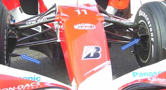
Figure 1: Front view of a Formula 1 car showing the inboard brake ducts (highlighted by blue arrows) used to cool the brake assembly.
Due to the time constraints imposed by the racing schedule, Formula 1 teams routinely partner with academic institutions to dig deeper into the physics and answer fundamental questions concerning the airflow around the car. An example of this has been the collaboration between Toyota F1 and Stanford University. The Stanford group was asked to investigate the flow around an isolated tire to identify the dynamics of the flow structure in the wake, determine if computer simulations match experimental measurements and understand under which circumstances the flow becomes asymmetrical with respect to a vertical plane that cut the tire in half. In spite of the broad knowledge regarding the aerodynamics of bluff bodies, the flow distortion introduced by the tire rotation, the interactions between the rubber and the ground under load, the effect of the air captured and then released by the brake system, and, in general the uncertainties related to the unknown geometry of the tire, pose tremendous challenges to a complete understanding.
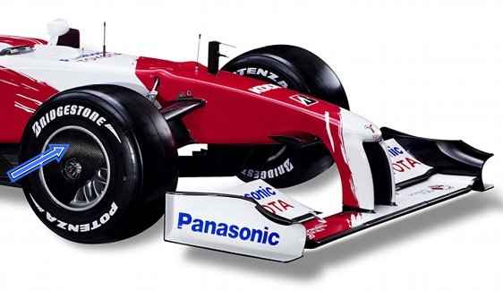
Figure 2: Side view of Toyota TF109 front end showing the outboard stationary wheel cover highlighted by the blue arrow. (Photo Courtesy of Toyota Formula 1)
The airflow around Formula 1 racecars is dominated by the presence of massive, exposed tires. The performance of the engine radiator and the back wing are determined by the flow structures originating on the front tires and in their near wake. Moreover, the brake system requires active cooling and a complex set of inlets and ducts are carved within the wheel (see Fig. 1) to preserve the braking efficiency. During last year’s championship, wheel covers (see Fig. 2) emerged as a competitive advantage and were employed rapidly by all teams. What is their role? How effective are they in increasing the brake cooling? Can they alter the flow in the wake of the tire and, therefore, act as an aerodynamic device? These are the types of questions engineers routinely try to answer.
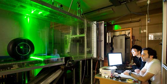
Figure 3: Experimental rolling road facility at Stanford. The green light immediately behind the isolated Formula 1 tire is the Particle Image Velocimetry plane used to extract velocity vectors from the wake of the tire. Pictured here are Kin Lo (left) and Emin Issakhanian (right) who are PhD students working in John Eaton's group. (Photo Courtesy of Mechanical Engineering at Stanford).
The Toyota-Stanford collaboration, for the first time, aimed at a detailed experimental investigation (using Particle Image Velocimetry [1], Fig. 3) and high-fidelity simulation (using Large Eddy Simulation [2], Fig 4) of a realistic F1 wheel including the tire deformation and the entire brake duct assembly. The simulations were performed on hundreds of CPUs for weeks at a time, and provided a vivid representation of the wake airflow (see movies below) and the presence of highly coherent structures, leading to quantitative understanding of the time-scale associated to the motion.
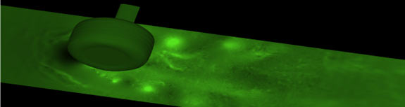
Figure 4: Large Eddy Simulation showing pressure contours 2 cm above the ground plane for an isolated stationary tire. The lighter green dots emanating from the contact patch of the tire are low pressure vortical structures.
Not surprisingly, the results of the LES simulations, confirmed by the PIV measurements, illustrate that unsteadiness, large-scale separation, and longitudinal vortical structures dominate the turbulent airflow behind the tire. The flow is very unstable and has the tendency to fluctuate from side to side. The results also show that there is a region of separated flow close to the back of the tire where air particles recirculate and travel forward faster than the car moves. Finally, the simulations show that a system of counter-rotating vortices overwhelms the wake of the isolated tire very far downstream. Additional simulations and experiments also confirmed the fundamental effect of tire rotation; specifically, the presence of a very strong downwash in the wake of a stationary tire which leads to only limited recirculation and thus to airflow that is not representative of realistic racecar conditions.
A large part of the research has been focused on determining the cause of the observed asymmetry in the strength of the counter-rotating vortices in the wake. The simulations show conclusively that the transverse flow determined by the brake system and, in particular, the flow exiting the outboard rotating spokes fundamentally alters the near wake structure. The air is sucked in by the brake inlet duct on the inboard side of the car, and spat out the outboard side of the car. As a result, the outboard vortex is reduced in size and displaced towards the ground, as illustrated in Fig. 5.
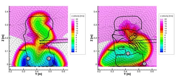
Figure 5: Numerical simulation of a plane downstream of a rotating Formula 1 tire for the case where all passages inside the tire have been blocked off (left) and for the true configuration where airflow is allowed to travel through the wheel hub (right). When airflow is allowed to freely move inside the hub, air travels from left to right (inboard to outboard) increasing the size and intensity of vortex 'A'. As a result vortex 'B' is displaced closer to the ground and looses almost all of its intensity.
Finally, an important aspect of the simulation work was the quantification of the effect of geometrical uncertainties in the definition of the tire geometry. The aerodynamic load produces a deformation that is difficult to determine because of the extreme complexity of the interaction between the rubber and the road. Constructing a parametric model of the tire proved that the uncertainty in the contact patch geometry dominates the wake airflow only in the case of a stationary (non rotating) tire simulation.
For F1 racecars traveling at 200mph, the wheels are not just about the grip; understanding the airflow over the tire and inside the wheel plays an important role in keeping teams successful.